Difference between revisions of "Multiple polarizers experimental apparatus"
Ist1102577 (talk | contribs) |
|||
| (89 intermediate revisions by 3 users not shown) | |||
| Line 1: | Line 1: | ||
=Apparatus description= | =Apparatus description= | ||
| − | The setup for the construction of the multiple polarizers twin experiment is composed of three main components: (i) the supporting 3D printed plastic parts whose schematics are available here, (ii) a | + | {| |
| + | |[[File:exploded_kit_view.png|thumb|x250px|Left|Exploded view of the experimental kit.]] | ||
| + | |[[File:exploded_kit_view_1.png|thumb|x250px|Left|Exploded view of the experimental kit.]] | ||
| + | |} | ||
| + | |||
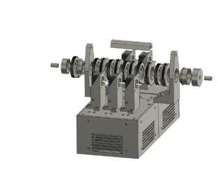
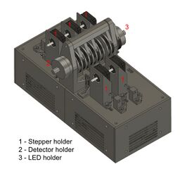
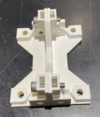
| + | The setup for the construction of the multiple polarizers twin experiment is composed of three main components: (i) the supporting 3D printed plastic parts whose schematics are available here, (ii) a Raspberry Pi running the control software over the internet and performing the video streaming and (iii) the low-level slave controller electronics comprising the sensing and the experiment motorisation. | ||
| + | |||
| + | =Mechanical Assembly= | ||
| + | |||
| + | {| | ||
| + | |[[File:Imagem_Experiência_1.jpg|thumb|x250px|Top|Top view of the experiment]] | ||
| + | |[[File:Imagem_Experiência_2.jpg|thumb|x250px|Top|Front view of the experiment]] | ||
| + | |} | ||
| + | |||
| + | In this section, the mechanical assembly of the experiment is explained in detail so that it can be used correctly. | ||
| + | |||
| + | ==Order of assembly== | ||
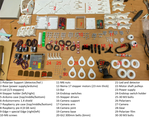
| − | + | 1. Check if all the parts needed to assemble the mechanical structure of the experiment are available. | |
| − | |||
{| | {| | ||
| − | + | |[[File:parts_needed_.png|thumb|x400px|Top|Parts needed for the assembly]] | |
| − | |[[File: | + | |} |
| − | | | + | The following table can be used to check the number of parts to be printed and if supports are needed: |
| − | | | + | {| class="wikitable" |
| + | ! Name !! Description !! Folders !! Number of parts !! Material !! Supports: necessary | ||
| + | |- | ||
| + | | Edge || Edge that supports the corners of the box || Structural Components || 6 || PLA || No | ||
| + | |- | ||
| + | | Edge Special Left || Special edge || Structural Components || 1 || PLA || No | ||
| + | |- | ||
| + | | Edge Special Right || Special edge || Structural Components || 1 || PLA || No | ||
| + | |- | ||
| + | | Larger Face || Box face along the length || Lids || 3 || PLA || No | ||
| + | |- | ||
| + | | Face Power Supply || Box face along length with cable hole || Lids || 1 || PLA || No | ||
| + | |- | ||
| + | | Smaller Face || Box face along the width || Lids || 2 || PLA || No | ||
| + | |- | ||
| + | | Power Supply Base || Bottom of the box with the power supply || Eletronics || 1 || PLA || No | ||
| + | |- | ||
| + | | Arduino Base || Arduino case || Eletronics || 1 || PLA || No | ||
| + | |- | ||
| + | | Arduino Case Top || Arduino case || Eletronics || 1 || PLA || No | ||
| + | |- | ||
| + | | Arduino Case Bottom || Arduino case || Eletronics || 1 || PLA || No | ||
| + | |- | ||
| + | | Raspberry Pie Case Middle || Raspberry Pie Box || Eletronics || 1 || PLA || No | ||
| + | |- | ||
| + | | Raspberry Pie Case Top || Raspberry Pie Box || Eletronics || 1 || PLA || No | ||
| + | |- | ||
| + | | Raspberry Pie Case Bottom || Raspberry Pie Box || Eletronics || 1 || PLA || No | ||
| + | |- | ||
| + | | Lid 2 Steppers || Box top that supports two motors || Polarizer Assembly || 1 || PLA || No | ||
| + | |- | ||
| + | | Lid 3 Steppers || Box top that supports two motors || Polarizer Assembly || 1 || PLA || No | ||
| + | |- | ||
| + | | Stepper_holder_left || Stepper motor support, compatible with the box cover with 2 supports || Polarizer Assembly || 1 || PLA || No | ||
| + | |- | ||
| + | | Stepper_holder_right || Stepper motor support, compatible with the box cover with 3 supports || Polarizer Assembly || 1 || PLA || No | ||
| + | |- | ||
| + | | Polarizer Support Detector || Support for the polarizer assembly, detector side || Polarizer Assembly || 1 || PLA || No | ||
| + | |- | ||
| + | | Polarizer Support led || Support for the polarizer assembly, emitter side || Polarizer Assembly || 1 || PLA || yes, for the pins that secure the polarizer | ||
| + | |- | ||
| + | | Bar || Support bar for polarizer supports; adjusts compression exerted || Polarizer Assembly || 1 || PLA || No | ||
| + | |- | ||
| + | | Gear || Gear wheel that fits behind each polarizer || Polarizer Assembly || 5 || PLA || No | ||
| + | |- | ||
| + | | Fixed Polarizer Holder || Fixed polarizer holder that fits into the polarizer Support led || Optical Assembly || 1 || PLA || yes | ||
| + | |- | ||
| + | | Detector Holder || Part that secures the LED adjuster || Optical Assembly || 1 || PLA || No | ||
| + | |- | ||
| + | | Detector Adjuster || Part that secures the LED holder || Optical Assembly || 1 || PLA || No | ||
| + | |- | ||
| + | | Led Ajuster || Part that secures the LED holder || Optical Assembly || 1 || PLA || yes, for the pins that secure the polarizer | ||
| + | |- | ||
| + | | Led Holder || LED and detector holder, which fits into the adjustment parts above || Optical Assembly || 2 || PLA || No | ||
| + | |- | ||
| + | | Base || Base for the camera || Camera_holder || 1 || || yes | ||
| + | |- | ||
| + | | Support || || Camera_holder || 3 || || yes | ||
| + | |- | ||
| + | | Arm || || Camera_holder || 1 || || yes | ||
| + | |- | ||
| + | | Joint || || Camera_holder || 1 || || yes | ||
|} | |} | ||
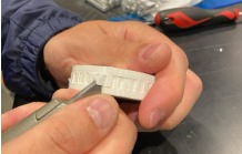
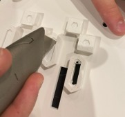
| + | 2. Peel the supports of the pulleys using pliers or an X-Acto knife. | ||
{| | {| | ||
| − | |[[File: | + | |[[File:peeled_support_1.jpg|thumb|x250px|Top|Peeling the support]] |
| − | |[[File: | + | |[[File:peeled_support_2.jpg|thumb|x250px|Top|Peeling the support]] |
|} | |} | ||
| − | |||
| + | 3. Put the belt on the peeled pulleys. | ||
| + | {| | ||
| + | |[[File:belt_on_pulley.jpg|thumb|x250px|Top|Belt on pulley]] | ||
| + | |} | ||
| − | + | 4. Connect the pulleys with the polarizer holders. Make sure to hear a “click” as only one side of the polarizer leads to this firm blockade. Additionally, place the polarizer inside the polarizer holder. (Don't forget to remove the polarizer protection if needed) | |
| − | |||
{| | {| | ||
| − | |[[File: | + | |[[File:pulley_polarizer.jpg|thumb|x250px|Top|Pulley and polarizer holder connection position]] |
| − | |[[File: | + | |[[File:pulley_polarizer_connected.jpg|thumb|x250px|Top|Pulley and polarizer holder connected]] |
| − | | | ||
|} | |} | ||
| + | |||
| + | 5. Repeat steps 2, 3 and 4 until a complete chain is achieved. You will get a cascaded polarizers set capable to move between each one. Do not forget to put the belts on, as they are not represented in the example picture. | ||
{| | {| | ||
| − | |[[File: | + | |[[File:pulley_polarizer_chain.jpg|thumb|x250px|Top|Chain of connected pulleys and polarizers]] |
|} | |} | ||
| − | |||
| − | + | 6. Cut the thin layers covering the holes of the main plates of the structure. | |
| + | {| | ||
| + | |[[File:thin_layer_cutting_process.jpg|thumb|x250px|Top|Main plates thin layers cutting process]] | ||
| + | |[[File:thin_layer_cut.jpg|thumb|x300px|Top|Main plates thin layers cut]] | ||
| + | |} | ||
| + | 7. Place two of the four pillars together and put the nuts in the specific holes on top of one of the pillars. | ||
{| | {| | ||
| − | |[[File: | + | |[[File:nuts_on_pillars.jpg|thumb|x250px|Top|Nuts placed on the pillar]] |
| − | |||
|} | |} | ||
| − | + | 8. Insert the bolts through the holes and bolt the two pillars together. | |
| + | {| | ||
| + | |[[File:bolts_on_pillars.jpg|thumb|x250px|Top|Bolts placed on the pillar]] | ||
| + | |[[File:pillars_bolted_together.jpg|thumb|x250px|Top|Pillars bolted together]] | ||
| + | |} | ||
| − | + | 9. Place the main plates next to each other. | |
| + | {| | ||
| + | |[[File:main_plates_placement.jpg|thumb|x250px|Top|Placement of the main plates (same as shown in the step 1 image)]] | ||
| + | |} | ||
| − | + | 10. Place the bolted pillars on the side of the junction of the two plates. | |
{| | {| | ||
| − | |[[File: | + | |[[File:junction_placement.jpg|thumb|x250px|Top|Placement of the pillars]] |
|} | |} | ||
| − | + | ||
| + | 11. Place the chain support on the other side of the main plates, so that they are in opposite positions. Check if the chain support is placed on top of the hexagonal holes. | ||
{| | {| | ||
| − | |[[File: | + | |[[File:chain_support_opposite_to_pillars.jpg|thumb|x250px|Top|Placement of the chain support]] |
| − | |[[File: | + | |[[File:chain_support_in_position.jpg|thumb|x250px|Top|Placement of the chain support]] |
|} | |} | ||
| − | + | ||
| + | 12. Place the nuts on the chain support inside the “boxes” closest to the chain support “wall”. | ||
{| | {| | ||
| − | |[[File: | + | |[[File:nuts_placement.png|thumb|x250px|Top|Chain support nuts placement]] |
|} | |} | ||
| − | + | ||
| + | 13. Insert the bolts through the holes on the bolted pillars and bolt the pillars, the main plates and the chain support together. | ||
{| | {| | ||
| − | |[[File: | + | |[[File:bolts_placement.png|thumb|x250px|Top|Insert the bolts through the highlighted holes]] |
| − | |||
|} | |} | ||
| − | + | ||
| + | 14. Insert the nuts inside the other holes of the chain support. | ||
| + | |||
| + | 15. Insert the bolts through the main plates and fully bolt the chain support to the main plates. | ||
{| | {| | ||
| − | |[[File: | + | |[[File:bolt_chain_support.jpg|thumb|x250px|Top|Bolt the chain support to the main plates and the pillars]] |
|} | |} | ||
| − | + | ||
| + | 16. Repeat steps 7 and 8. | ||
| + | |||
| + | 17. Go to the opposite side of the main plates and place the bolted pillars under the circular holes. | ||
| + | |||
| + | 18. Place the nuts inside the top holes of the bolted pillars. | ||
| + | |||
| + | 19. Insert the bolt through the main plates and bolt them together with the pillars. | ||
{| | {| | ||
| − | |[[File: | + | |[[File:bolt_the_other_pillars.jpg|thumb|x250px|Top|Bolt the other pillars]] |
| − | |||
|} | |} | ||
| − | + | ||
| + | 20. Connect the chain with the bolted chain support and with the loose one, as well. | ||
{| | {| | ||
| − | |[[File: | + | |[[File:chain_in_place.jpg|thumb|x250px|Top|Chain structure placement]] |
|} | |} | ||
| − | + | ||
| + | 21. Place the nuts inside the specific “boxes” of the loose chain support. | ||
| + | |||
| + | 22. Insert the bolts through the holes in the main plates to connect the loose chain support to the main plates. | ||
{| | {| | ||
| − | |[[File: | + | |[[File:fully_bolted_chain.jpg|thumb|x250px|Top|Bolted chain structure]] |
| − | |||
|} | |} | ||
| − | + | ||
| − | + | 23. Pick one of the pillars and place the nut inside the middle “box”. | |
{| | {| | ||
| − | |[[File: | + | |[[File:nut_middle_box.jpg|thumb|x250px|Top|Nut inside the middle "box"]] |
|} | |} | ||
| − | + | ||
| + | 24. Place it beneath the main plates in one of the corners. | ||
| + | |||
| + | 25. Insert the bolt through the main plates to bolt them to the pillar. | ||
{| | {| | ||
| − | |[[File: | + | |[[File:corner_placement.jpg|thumb|x250px|Top|Corner placement]] |
| − | |||
|} | |} | ||
| − | + | ||
| − | + | 26. Repeat steps 23, 24 and 25 until the four corners of the structure are supported. | |
| − | + | ||
| − | + | 27. Remove the small pillars on the surface facing downwards of the main plate to allow nuts to be inserted into those “boxes.” | |
{| | {| | ||
| − | |[[File: | + | |[[File:remove_small_pillars_1.jpg|thumb|x250px|Top|Small pillars removal]] |
| + | |[[File:remove_small_pillars_2.jpg|thumb|x250px|Top|Small pillars removal]] | ||
|} | |} | ||
| − | + | ||
| − | + | 28. Insert the nuts inside those “boxes”. | |
| − | |||
| − | |||
{| | {| | ||
| − | |[[File: | + | |[[File:nuts_on_main_plate_1.jpg|thumb|x250px|Top|Nuts placement on the main plate]] |
| + | |[[File:nuts_on_main_plate_2.jpg|thumb|x250px|Top|Nuts placement on the main plate]] | ||
|} | |} | ||
| − | + | ||
| + | 29. Place the stepper holder above the holes. | ||
| + | |||
| + | 30. Insert the bolts through the holes of the stepper holder in order to connect it to the main plates. | ||
{| | {| | ||
| − | |[[File: | + | |[[File:stepper_holder_placement.jpg|thumb|x250px|Top|Stepper holder placement on the main plate]] |
|} | |} | ||
| − | + | ||
| − | + | 31. Repeat steps 28, 29 and 30 for the other four stepper holders. | |
| + | |||
| + | 32. Place the stepper motor on the stepper holder by first putting the wires through the top and bottom holes. Then, hear a click to ensure the stepper motor is well fixed. NOTE: the cable connection may vary depending on the driver, it is not reliable to use cable colors. | ||
{| | {| | ||
| − | |[[File: | + | |[[File:wires_placement.jpg|thumb|x250px|Top|Wires entering position]] |
|} | |} | ||
| − | + | ||
| + | 33. Repeat step 32 for the other 4 stepper motors. | ||
{| | {| | ||
| − | |[[File: | + | |[[File:stepper_placement.jpg|thumb|x250px|Top|Stepper motor placement]] |
|} | |} | ||
| − | + | ||
| − | + | 34. Place the belt in the pulley. | |
| + | |||
| + | 35. Connect the pulley (with the belt) to the stepper motor. | ||
{| | {| | ||
| − | |[[File: | + | |[[File:motor_placement.jpg|thumb|x250px|Top|Pulley placement with the belt on]] |
|} | |} | ||
| − | + | ||
| − | + | 36. Tighten the pulley. | |
{| | {| | ||
| − | |[[File: | + | |[[File:motor_tightened.jpg|thumb|x250px|Top|Tightening of the pulley]] |
| − | |||
|} | |} | ||
| − | + | ||
| + | 37. Adjust the stepper holder position to ensure the belt is not loose. | ||
{| | {| | ||
| − | |[[File: | + | |[[File:adjust_stepper_holder_position.jpg|thumb|x250px|Top|Stepper holder too close to the chain (Belt is loose)]] |
| − | |||
|} | |} | ||
| − | + | ||
| − | + | 38. Tighten the bolts of the stepper holder to fix it. | |
{| | {| | ||
| − | |[[File: | + | |[[File:stepper_holder_position_adjusted.jpg|thumb|x250px|Top|Stepper holder in the correct position]] |
|} | |} | ||
| − | + | ||
| − | + | 39. Repeat steps 34, 35, 36, 37 and 38 for the other four stepper holders. | |
| + | |||
| + | 40. Assembly completed. | ||
| + | |||
| + | =Electronic circuit= | ||
| + | |||
| + | The experiment has two main electronic parts, the drivers (1) for the step-motors and the light source and detection (2). | ||
| + | |||
| + | ==Electronic component assembly== | ||
| + | |||
| + | 1. Check if all the parts needed for the electronic component assembly of the experiment are available. | ||
{| | {| | ||
| − | |[[File: | + | |[[File:electric_assembly_parts.jpg|thumb|Parts needed for the electronic component assembly.]] |
|} | |} | ||
| − | + | ||
| + | 2. Get the left floor of the electronic component (see the image below) and use a soldering iron to insert the heat inserts in the floor's holes, through the thermal insertion process. | ||
| + | {| | ||
| + | |[[File:electric_assembly_left_floor.jpg|thumb|Left floor of the electronic component.]] | ||
| + | |[[File:insercao_termica.jpg|thumb|Thermal insertion.]] | ||
| + | |} | ||
| + | |||
| + | 3. Get the Arduino Mega box (see the image below) and bolt it to the floor. | ||
{| | {| | ||
| − | |[[File: | + | |[[File:arduino_case.jpg|thumb|Arduino Mega box.]] |
| + | |} | ||
| + | |||
| + | 4. Use a soldering iron to insert the heat inserts in the box holes, through the thermal insertion process. | ||
| + | {| | ||
| + | |[[File:arduino_case_holes.jpg|thumb|Holes in the Arduino Mega box.]] | ||
| + | |} | ||
| + | |||
| + | 5. Select a heat sink. | ||
| + | {| | ||
| + | |[[File:Heat_Sink.jpg|thumb|Heat Sink.]] | ||
| + | |} | ||
| + | |||
| + | 6. Remove the paper protection. | ||
| + | {| | ||
| + | |[[File:paper_protection_removal.jpg|thumb|Remove the paper protection.]] | ||
| + | |[[File:paper_removed.jpg|thumb|Remove the paper protection.]] | ||
| + | |} | ||
| + | |||
| + | 7. Glue the heat sink to the step-motor driver. | ||
| + | {| | ||
| + | |[[File:heat_sink_placement.jpg|thumb|Heat sink placement.]] | ||
| + | |[[File:heat_sink_placed.jpg|thumb|Heat sink placed.]] | ||
| + | |} | ||
| + | |||
| + | 8. Repeat the steps 1, 2 and 3 for the other five step-motor drivers. | ||
| + | |||
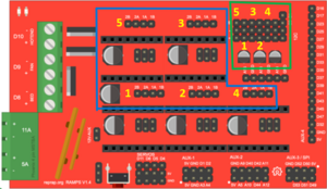
| + | 9. Place the step-motor driver on the RAMPS 1.4 (RepRap Arduino Mega Pololu Shield) | ||
| + | {| | ||
| + | |[[File:Placa_RAMPS.jpg|thumb|RAMPS 1.4.]] | ||
| + | |[[File:Placa_RAMPS_software.png|thumb|RAMPS 1.4 (software view).]] | ||
| + | |} | ||
| + | |||
| + | 10. Check if the step-motor driver is well placed, meaning its ground connection is as shown in the image below and that the bolt (potentiometer) is on the opposite side of the power supply (in the case of the green and red step-motor drivers) or in the side of the power supply (in the case of the purple step-motor drivers). | ||
| + | {| | ||
| + | |[[File:drivers.png|thumb|Step-motor drivers models.]] | ||
| + | |[[File:driver_placement_software.png|thumb|Purple step-motor driver placement (software view).]] | ||
| + | |[[File:driver_placement_green.png|thumb|Purple and green step-motor driver placement.]] | ||
| + | |} | ||
| + | |||
| + | 11. Repeat the steps 5 and 6 for the other five step-motor drivers. | ||
| + | {| | ||
| + | |[[File:driver_placement.jpg|thumb|RAMPS 1.4 with the step-motor drivers in place.]] | ||
|} | |} | ||
| − | + | ||
| − | + | 12. Connect the switches to the wires. | |
| + | {| | ||
| + | |[[File:switches_wires.jpg|thumb|Switches connection to the wires.]] | ||
| + | |} | ||
| + | |||
| + | 13. Place the switches in the switch holder. Ensure you hear a "click" to confirm they are well positioned. | ||
| + | {| | ||
| + | |[[File:switches_placement.png|thumb|Switches positioning in the holder.]] | ||
| + | |} | ||
| + | |||
| + | 14. Connect the step-motor wires to the step-motor drivers through the RAMPS 1.4. Check the pinouts connection through its colour and according to the information provided in the subsection [[#Step-motor drivers|Step-motor drivers]]. | ||
{| | {| | ||
| − | |[[File: | + | |[[File:stepper_wires_placement.jpg|thumb|Wires connection in the RAMPS 1.4.]] |
| + | |[[File:stepper_array.png|thumb|Top-view of kit:numbering of thre steppers and respective switches.]] | ||
| + | |[[File:switches_wires_placement_software.png|thumb|Switches' wires (green) and step-motor wires (blue) (software view).]] | ||
|} | |} | ||
| − | + | ||
| + | 15. Assemble the detector and photodiode electric circuit. | ||
| + | {| | ||
| + | |[[File:photodiode_circuit.jpg|thumb|Detector and photodiode electric circuit schematics.]] | ||
| + | |} | ||
| + | |||
| + | 16. Place the electric circuit in the box corner, position it according to the holes, and bolt it. | ||
{| | {| | ||
| − | |[[File: | + | |[[File:electric_circuit.jpg|thumb|Switchers positioning in the switch holder.]] |
|} | |} | ||
| − | + | ||
| + | 17. Get the top part of the Arduino Mega box and bolt it to the bottom part (attention to the wires when closing the box). | ||
{| | {| | ||
| − | |[[File: | + | |[[File:arduino_top_case.jpg|thumb|Top part of the Arduino Mega box.]] |
|} | |} | ||
| − | + | ||
| + | 18. Repeat the step 2 for the right floor. | ||
| + | {| | ||
| + | |[[File:electric_assembly_right_floor.jpg|thumb|Right floor of the electronic component.]] | ||
| + | |} | ||
| + | |||
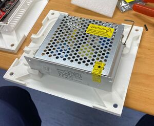
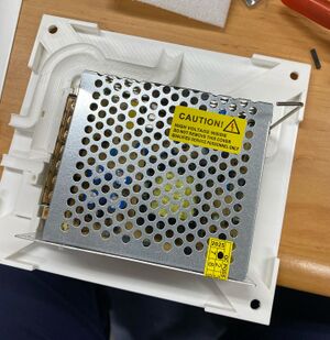
| + | 19. Place the power supply on the right floor and secure it with bolts. | ||
{| | {| | ||
| − | |[[File: | + | |[[File:power_supply.jpg|thumb|Power supply.]] |
| + | |[[File:power_supply_top_view.jpg|thumb|Top view of the power supply.]] | ||
|} | |} | ||
| − | |||
| − | |||
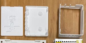
| − | + | 20. Get the bottom part of the Raspberry Pi box and repeat the step 4. | |
| + | {| | ||
| + | |[[File:raspberry_pi_case.jpg|thumb|Raspberry Pi box.]] | ||
| + | |} | ||
| + | |||
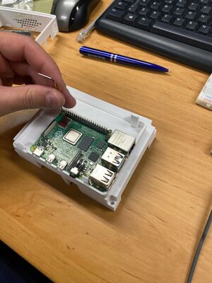
| + | 21. Bolt the Raspberry Pi to the box. | ||
| + | {| | ||
| + | |[[File:raspberry_pi.jpg|thumb|Raspberry Pi.]] | ||
| + | |} | ||
| + | |||
| + | 22. Connect the middle part of the Raspberry Pi box to the bottom part. | ||
| − | + | 23. Place the cover to close the box. | |
==Step-motor drivers== | ==Step-motor drivers== | ||
| + | [[file:StepMotorCable.jpg | Numbering of the step-motor cable connection|thumb|120px]] | ||
| + | The step-motor drivers can have multiple design outputs according to the producer. The stepper pin-outs are numbered from 1-6, from left to right from the front view (shaft pointing you, connector downwards). | ||
| + | The driver's location on the arduíno mezzanine relates to the step-motor according to the schema below: | ||
| + | |||
| + | {| border="1" style="width:150px; height:150px; text-align:center;" | ||
| + | |+ Driver to step-motor link | ||
| + | | style="width:66px; height:66px;" | 5 | ||
| + | | style="width:66px; height:66px;" | 3 | ||
| + | | style="width:66px; height:66px;" | N/A | ||
| + | |- | ||
| + | | style="width:66px; height:66px;" | 1 | ||
| + | | style="width:66px; height:66px;" | 2 | ||
| + | | style="width:66px; height:66px;" | 4 | ||
| + | |} | ||
| + | |||
| + | By using a proper cable the connections should follow the table below: | ||
| + | {| border="1" style="text-align: center;" | ||
| + | |+ Driver to step-motor connections | ||
| + | |- | ||
| + | !Motherboard pin-out | ||
| + | !Cable color | ||
| + | !Step-motor pin (A4988) | ||
| + | !Step-motor pin (DRV8825) | ||
| + | |- | ||
| + | |2B | ||
| + | |Red | ||
| + | | | ||
| + | |6 | ||
| + | |- | ||
| + | |2A | ||
| + | |Green | ||
| + | | | ||
| + | |3 | ||
| + | |- | ||
| + | |1A | ||
| + | |Black | ||
| + | | | ||
| + | |1 | ||
| + | |- | ||
| + | |1B | ||
| + | |Blue | ||
| + | | | ||
| + | |4 | ||
| + | |- | ||
| + | |} | ||
==Light source and detection== | ==Light source and detection== | ||
[[File:NPolarizersElectronicCircuit.png|thumb|Schematic for the LED PWM connection to the A4 pin of the controller board and the filter for the photodiode detection circuit.]] | [[File:NPolarizersElectronicCircuit.png|thumb|Schematic for the LED PWM connection to the A4 pin of the controller board and the filter for the photodiode detection circuit.]] | ||
| − | The red LED is | + | The red LED is fed by a PWM output pin (A4) from the main controller board, which allows for a variable light intensity. The default PWM from the board has a 490Hz modulation in steps of 1/256, giving a resolution of less than 0.5%. |
| + | |||
| + | After passing the cascade of polarizers, the signal is detected by a photodiode. This photodiode is inversely biased with a resistor to ground in order to have a zero signal when no light is present. | ||
| − | + | As the signal is modulated and its frequency has to be removed we use a low-pass first order RC-filter. As the time constant is ~1s, is necessary to delay the first acquisition for the settling of the circuit voltages. Then, as the signal varies smoothly and slowly due to the polarizer rotation, and oversampling is in place, a much lower settling time is needed. | |
=Optical path= | =Optical path= | ||
| − | + | [[File:Polarizer optical circuit.png|thumb|x120px|Top|Optical path showing the collimating system to let the light pass through the cascade of polarizers in parallel rays.]] | |
| + | The optical path consists of a light source (1) (red LED) placed in the focal point of a semi-spherical lens (2) where the light rays are collimated in a parallel beam of light. | ||
| + | |||
| + | Then it is polarized by the fixed polarizer (3) before entering the cascade of variable tilt polarizers (4). This chain will dim the light according to each polarizer angle and it passes the second lens in order to focus on the detector, a photodiode (6). | ||
| + | |||
| + | Before reaching the photodiode, light may pass a red filter (5) to narrow the bandwidth and limit external noise. This filter is not damned necessary and can be replaced by red cellophane paper or even absent in case of a fully opaque plastic structure. | ||
==Optical path alignment== | ==Optical path alignment== | ||
| − | The main body of the device has the light propagating in parallel rays through the cascade of polarizers. Those rays later | + | The main body of the device has the light propagating in parallel rays through the cascade of polarizers. Those rays are later focused on the sensor (photo-diode). It is crucial for a good signal-to-noise reading to have the system perfectly aligned. For that end, the linear position of the emitting LED and the photo-diode receiver can be adjusted according to the following procedure: |
| − | # | + | #First assemble the system lens and the light source (LED); |
#Energize the LED and follow the emerging circular image from the output, eg. projecting it in a wall a couple of meters apart; | #Energize the LED and follow the emerging circular image from the output, eg. projecting it in a wall a couple of meters apart; | ||
| − | #Move the LED position in order to have an output image | + | #Move the LED position in order to have an output image closer to the size of the exit circle (~30mm); |
#Install the structure for the cascade of polarizers without any lens or hard film in it; | #Install the structure for the cascade of polarizers without any lens or hard film in it; | ||
#Put in place the second collimating lens in order to focus the light in the photo-diode; | #Put in place the second collimating lens in order to focus the light in the photo-diode; | ||
| Line 195: | Line 453: | ||
Once the support structure is in place, is necessary to calibrate the absolute position of each polarizer; effectively all the polarizers will have a small offset giving a systematic error. It is important to note these angular value that maximizes the transmissivity. | Once the support structure is in place, is necessary to calibrate the absolute position of each polarizer; effectively all the polarizers will have a small offset giving a systematic error. It is important to note these angular value that maximizes the transmissivity. | ||
| − | The first polarizer is fixed and shall be positioned with a couple of degrees in order to avoid starting the experiment from a maximum, allowing for | + | The first polarizer is fixed and shall be positioned with a couple of degrees in order to avoid starting the experiment from a maximum, allowing for easy observation of such maxima. Consider having it around ~15º to 30º and well secured, eventually with glue. |
| − | Then start the calibration procedure by inserting the second polarizer and rotating it | + | Then start the calibration procedure by inserting the second polarizer and rotating it until the maximums are detected and measured (usually two). Take note of their value and leave the second polarizer at rest in the measured position. Now insert the third polarizer and repeat the procedure for the detection of the maximums and do this for the rest of them. |
| − | Every time a hard film or lens is installed it has to be firmly fixed or glued. If glue is used it ''must not damage the | + | Every time a hard film or lens is installed it has to be firmly fixed or glued. If glue is used it ''must not damage the polarizer film''. |
You will end up with a table of maximum transmission angles, leading to the reference value of maximum intensity in the cascade of polarizers. | You will end up with a table of maximum transmission angles, leading to the reference value of maximum intensity in the cascade of polarizers. | ||
| − | Later, when performing the experiments | + | It is provided in the firmware a function able to rotate a set of polarizers in conjunction with each other. With this procedure local maximums can be inferred to confirm the previous determined values. In fact, if a group of the last polarizers are made to rotate in conjunction, the maximum is dictated by the first one to rotate in order to the last one fixed. |
| + | |||
| + | Later, when performing the experiments these values of offsets must be considered in order to eliminate the systematic error of the system. | ||
| + | |||
| + | =Software = | ||
| + | To properly use the experiment, commands and data retrieval have to be in place. This can be achieved in two ways acting through the serial connection to the Arduino Mega. | ||
| + | |||
| + | The firmware existing in the Arduido is able to (i) configure the experiment (ii) run and retrieve the generated data and (iii) execute some specialized function in order to test, calibrate and maintain the experiment. To interface with the firmware it can be used (i) a python proxy code (high-level software layer) capable of interoperating with the FREE server or (ii) a terminal emulator like Minicom available for Linux that allows you to send and receive data over the serial connection. | ||
| + | |||
| + | |||
| + | ==Raspberry FREE proxy== | ||
| + | The Raspberry Pi is responsible for transmitting the video feed of the experiment and establishing communication with the FREE-Server by using a proxy interface. The FREE hosts the graphical user interface (GUI) to the clients. This section provides a concise overview of the procedure used to control all electronic components via the Arduino, as well as the communication protocols between the Arduino and the FREE-Server. | ||
| + | |||
| + | ===Communication model between the FREE-Server and the Raspberry PI=== | ||
| + | |||
| + | The communication between the server and the experiment follows the elab’s structured protocol that enables real-time interaction and data exchange. The central server, Exp Server, acts as an intermediary between users and the experimental apparatus (RPi Server). Users interact with Exp Server via a web interface made with Django, a high-level Python web framework, to configure and control the experiment parameters, while Exp Server directly relays these commands to the experimental setup. The communication between Exp Server and RPi Server occurs over the internet using JSON-formatted messages, ensuring flexibility across different experimental configurations. Authentication is performed at the connection stage, where the RPi Server transmits an ID and a secret key for verification. Once authenticated, the Exp Server sends an experiment-specific configuration file to the RPi Server, which then establishes communication with the local controller using the predefined protocol [7]. Throughout the experiment, the RPi Server continuously exchanges status updates, experimental results, and error messages with the XP server, ensuring synchronized operation and real-time data accessibility for users. | ||
| + | |||
| + | ===Communication model between the Raspberry PI and the Arduino Mega=== | ||
| + | To enable seamless communication between the Arduino and the Raspberry Pi 4, the protocol ReC Generic Drive 11 was implemented, allowing the external user to have full control over the experiment and its status through a set of commands. The ReC Generic Drive is a generic communication protocol designed for remote laboratories, facilitating interaction between a software driver and experimental hardware. It enables seamless communication over serial ports (RS232), using structured messages where driver commands are in lowercase and hardware responses in uppercase. | ||
| + | |||
| + | The protocol ensures synchronization through message handshaking and timeout handling, supporting functions like identification, configuration, data transmission, experiment configuration, and error reporting. | ||
| + | |||
| + | Fig. 11: ReC Generic Drive State-machine diagram of the driver [7] | ||
| + | |||
| + | By reading the Arduino’s serial port at a baud rate of 115200 bits per second, the user sends a bit string (ending with the character ’\r’). The configuration message is defined as: | ||
| + | cfg p0 p1 p2 p3 p4 p5 p6 p7\r | ||
| + | Where p0 defines the state of the LED (on or off), p1 p2 p3 p4 and p5 define the angle (in steps of 0.36◦) at which the experiment will start the sweep, p6 defines what polarizer will be sweeping (if does not pretend to sweep then p6 is 0) and p7 defines the limit angle of the polarizer being swept (also in steps of 0.36◦) at which the experiment will stop. | ||
| + | |||
| + | ==Firmware== | ||
| + | The programming was done using the C++ language without any external libraries. To declare a component in the code, one simply provides the corresponding input pin and accesses the enable function to initialize it, as well as the | ||
| + | ''isTrigger'' function to check whether the logical value read corresponds to the component’s trigger state. In this particular case, the switch is active on a LOW signal. Since all objects and respective components need to be initialized and turned off, each has corresponding enable/disable functions. Components connected to single read pins, declared as ''pinMode'' (such as switches and photodiodes), do not require a disable function since ''pinMode'' does not prevent reading the pins but rather helps define the type of input being processed. | ||
| + | |||
| + | In order to rotate the stepper motors, the operation consists of sending a pulse each time a rotation of 1.8◦ (0.36º effective) is desired. | ||
| + | Since different RPM values require different pulse intervals, the frequency of sent pulses must be calculated accordingly. | ||
| + | To execute a discrete sequence of steps based on a given angle in degrees, the rotate function was implemented. The motor rotates to the low nearest integer multiple of 1.8◦ to the provided angle. | ||
| + | |||
| + | The data acquisition interval is crucial for the final experiment since the goal is to optimize the user experience by minimizing waiting times when retrieving the intensity of light and scanning angle data. To address this, a global RPM of 600 revolutions per minute was used. With a scanning limit of 324◦ (as previously mentioned in Section III), the experimentally measured data acquisition time for scanning one or more polarizers simultaneously was approximately 40 seconds. | ||
| + | |||
| + | To further refine the voltage readings from the photodiode, an arithmetic mean of N points was implemented in the photodiode voltage reading function. By computing the arithmetic mean over 13 points of the value being measured, the standard deviation of this mean reduces the original standard deviation by ≈ 27.14%. This reduction was deemed acceptable for the experiment, as the data adjustment performed was successful, as will be observed in Section V). | ||
| − | |||
| − | |||
| − | |||
| − | |||
| − | |||
| − | |||
| − | |||
| − | |||
=Links= | =Links= | ||
| + | *[[Kit experimental de polarização da luz com múltiplos polarizadores | Portuguese version (Versão em Português)]] | ||
*[https://elab.vps.tecnico.ulisboa.pt:8000/execution/create/33/14 Direct link for the control room] | *[https://elab.vps.tecnico.ulisboa.pt:8000/execution/create/33/14 Direct link for the control room] | ||
*[[Light Polarization with multiple polarizers | Reference lesson]] | *[[Light Polarization with multiple polarizers | Reference lesson]] | ||
| + | *[https://www.printables.com/model/1293618-multi_polarizer_experiment Print your experiment] | ||
Latest revision as of 20:29, 26 August 2025
Contents
Apparatus description
The setup for the construction of the multiple polarizers twin experiment is composed of three main components: (i) the supporting 3D printed plastic parts whose schematics are available here, (ii) a Raspberry Pi running the control software over the internet and performing the video streaming and (iii) the low-level slave controller electronics comprising the sensing and the experiment motorisation.
Mechanical Assembly
In this section, the mechanical assembly of the experiment is explained in detail so that it can be used correctly.
Order of assembly
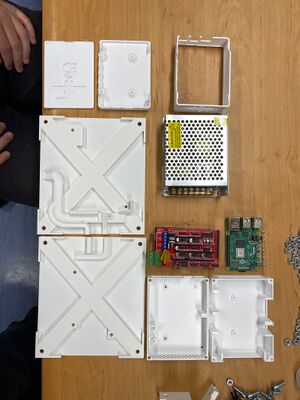
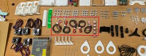
1. Check if all the parts needed to assemble the mechanical structure of the experiment are available.
The following table can be used to check the number of parts to be printed and if supports are needed:
| Name | Description | Folders | Number of parts | Material | Supports: necessary |
|---|---|---|---|---|---|
| Edge | Edge that supports the corners of the box | Structural Components | 6 | PLA | No |
| Edge Special Left | Special edge | Structural Components | 1 | PLA | No |
| Edge Special Right | Special edge | Structural Components | 1 | PLA | No |
| Larger Face | Box face along the length | Lids | 3 | PLA | No |
| Face Power Supply | Box face along length with cable hole | Lids | 1 | PLA | No |
| Smaller Face | Box face along the width | Lids | 2 | PLA | No |
| Power Supply Base | Bottom of the box with the power supply | Eletronics | 1 | PLA | No |
| Arduino Base | Arduino case | Eletronics | 1 | PLA | No |
| Arduino Case Top | Arduino case | Eletronics | 1 | PLA | No |
| Arduino Case Bottom | Arduino case | Eletronics | 1 | PLA | No |
| Raspberry Pie Case Middle | Raspberry Pie Box | Eletronics | 1 | PLA | No |
| Raspberry Pie Case Top | Raspberry Pie Box | Eletronics | 1 | PLA | No |
| Raspberry Pie Case Bottom | Raspberry Pie Box | Eletronics | 1 | PLA | No |
| Lid 2 Steppers | Box top that supports two motors | Polarizer Assembly | 1 | PLA | No |
| Lid 3 Steppers | Box top that supports two motors | Polarizer Assembly | 1 | PLA | No |
| Stepper_holder_left | Stepper motor support, compatible with the box cover with 2 supports | Polarizer Assembly | 1 | PLA | No |
| Stepper_holder_right | Stepper motor support, compatible with the box cover with 3 supports | Polarizer Assembly | 1 | PLA | No |
| Polarizer Support Detector | Support for the polarizer assembly, detector side | Polarizer Assembly | 1 | PLA | No |
| Polarizer Support led | Support for the polarizer assembly, emitter side | Polarizer Assembly | 1 | PLA | yes, for the pins that secure the polarizer |
| Bar | Support bar for polarizer supports; adjusts compression exerted | Polarizer Assembly | 1 | PLA | No |
| Gear | Gear wheel that fits behind each polarizer | Polarizer Assembly | 5 | PLA | No |
| Fixed Polarizer Holder | Fixed polarizer holder that fits into the polarizer Support led | Optical Assembly | 1 | PLA | yes |
| Detector Holder | Part that secures the LED adjuster | Optical Assembly | 1 | PLA | No |
| Detector Adjuster | Part that secures the LED holder | Optical Assembly | 1 | PLA | No |
| Led Ajuster | Part that secures the LED holder | Optical Assembly | 1 | PLA | yes, for the pins that secure the polarizer |
| Led Holder | LED and detector holder, which fits into the adjustment parts above | Optical Assembly | 2 | PLA | No |
| Base | Base for the camera | Camera_holder | 1 | yes | |
| Support | Camera_holder | 3 | yes | ||
| Arm | Camera_holder | 1 | yes | ||
| Joint | Camera_holder | 1 | yes |
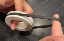
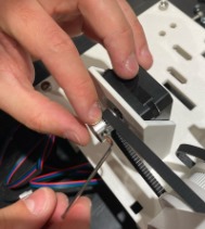
2. Peel the supports of the pulleys using pliers or an X-Acto knife.
3. Put the belt on the peeled pulleys.
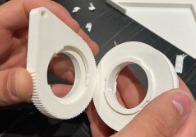
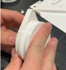
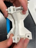
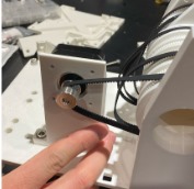
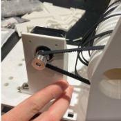
4. Connect the pulleys with the polarizer holders. Make sure to hear a “click” as only one side of the polarizer leads to this firm blockade. Additionally, place the polarizer inside the polarizer holder. (Don't forget to remove the polarizer protection if needed)
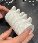
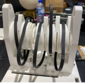
5. Repeat steps 2, 3 and 4 until a complete chain is achieved. You will get a cascaded polarizers set capable to move between each one. Do not forget to put the belts on, as they are not represented in the example picture.
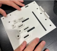
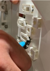
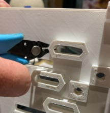
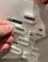
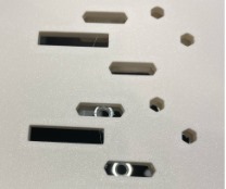
6. Cut the thin layers covering the holes of the main plates of the structure.
7. Place two of the four pillars together and put the nuts in the specific holes on top of one of the pillars.
8. Insert the bolts through the holes and bolt the two pillars together.
9. Place the main plates next to each other.
10. Place the bolted pillars on the side of the junction of the two plates.
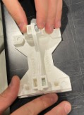
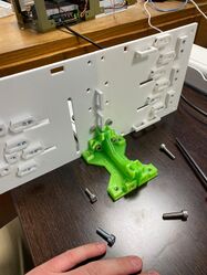
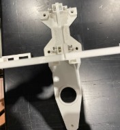
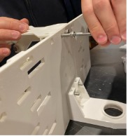
11. Place the chain support on the other side of the main plates, so that they are in opposite positions. Check if the chain support is placed on top of the hexagonal holes.
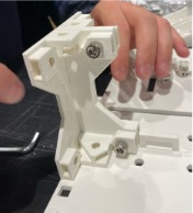
12. Place the nuts on the chain support inside the “boxes” closest to the chain support “wall”.
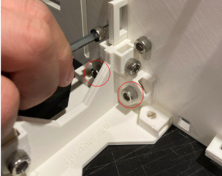
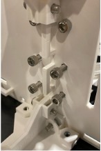
13. Insert the bolts through the holes on the bolted pillars and bolt the pillars, the main plates and the chain support together.
14. Insert the nuts inside the other holes of the chain support.
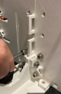
15. Insert the bolts through the main plates and fully bolt the chain support to the main plates.
16. Repeat steps 7 and 8.
17. Go to the opposite side of the main plates and place the bolted pillars under the circular holes.
18. Place the nuts inside the top holes of the bolted pillars.
19. Insert the bolt through the main plates and bolt them together with the pillars.
20. Connect the chain with the bolted chain support and with the loose one, as well.
21. Place the nuts inside the specific “boxes” of the loose chain support.
22. Insert the bolts through the holes in the main plates to connect the loose chain support to the main plates.
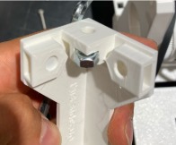
23. Pick one of the pillars and place the nut inside the middle “box”.
24. Place it beneath the main plates in one of the corners.
25. Insert the bolt through the main plates to bolt them to the pillar.
26. Repeat steps 23, 24 and 25 until the four corners of the structure are supported.
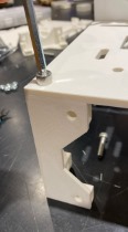
27. Remove the small pillars on the surface facing downwards of the main plate to allow nuts to be inserted into those “boxes.”
28. Insert the nuts inside those “boxes”.
29. Place the stepper holder above the holes.
30. Insert the bolts through the holes of the stepper holder in order to connect it to the main plates.
31. Repeat steps 28, 29 and 30 for the other four stepper holders.
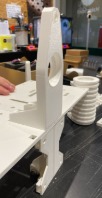
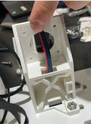
32. Place the stepper motor on the stepper holder by first putting the wires through the top and bottom holes. Then, hear a click to ensure the stepper motor is well fixed. NOTE: the cable connection may vary depending on the driver, it is not reliable to use cable colors.
33. Repeat step 32 for the other 4 stepper motors.
34. Place the belt in the pulley.
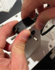
35. Connect the pulley (with the belt) to the stepper motor.
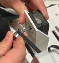
36. Tighten the pulley.
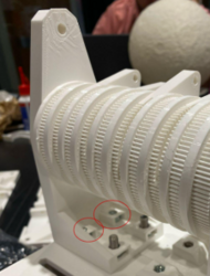
37. Adjust the stepper holder position to ensure the belt is not loose.
38. Tighten the bolts of the stepper holder to fix it.
39. Repeat steps 34, 35, 36, 37 and 38 for the other four stepper holders.
40. Assembly completed.
Electronic circuit
The experiment has two main electronic parts, the drivers (1) for the step-motors and the light source and detection (2).
Electronic component assembly
1. Check if all the parts needed for the electronic component assembly of the experiment are available.
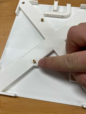
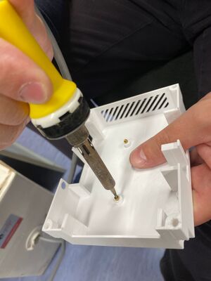
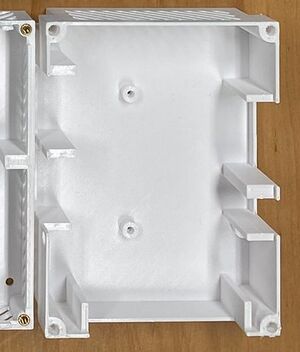
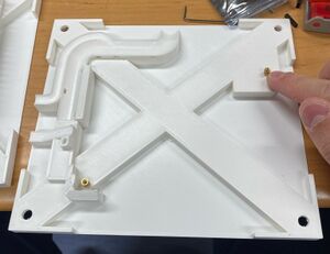
2. Get the left floor of the electronic component (see the image below) and use a soldering iron to insert the heat inserts in the floor's holes, through the thermal insertion process.
3. Get the Arduino Mega box (see the image below) and bolt it to the floor.
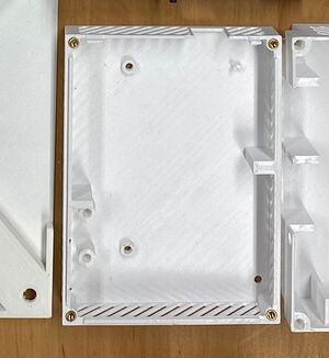
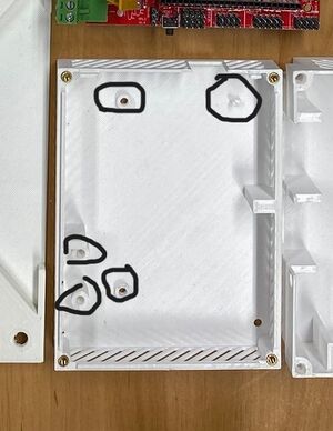
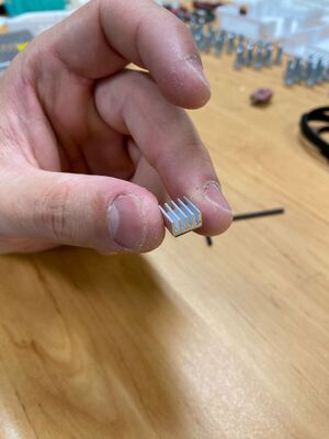
4. Use a soldering iron to insert the heat inserts in the box holes, through the thermal insertion process.
5. Select a heat sink.
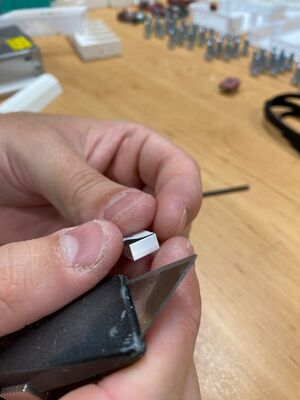
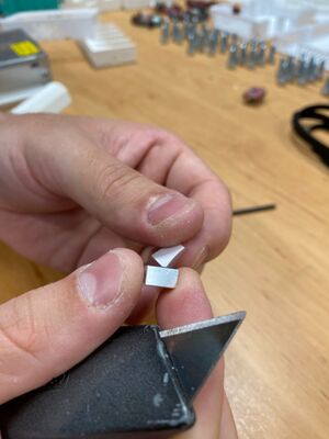
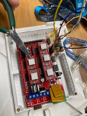
6. Remove the paper protection.
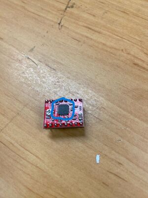
7. Glue the heat sink to the step-motor driver.
8. Repeat the steps 1, 2 and 3 for the other five step-motor drivers.
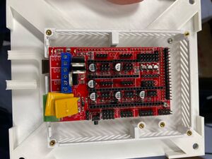
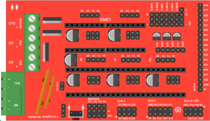
9. Place the step-motor driver on the RAMPS 1.4 (RepRap Arduino Mega Pololu Shield)
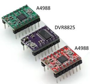
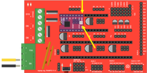
10. Check if the step-motor driver is well placed, meaning its ground connection is as shown in the image below and that the bolt (potentiometer) is on the opposite side of the power supply (in the case of the green and red step-motor drivers) or in the side of the power supply (in the case of the purple step-motor drivers).
11. Repeat the steps 5 and 6 for the other five step-motor drivers.
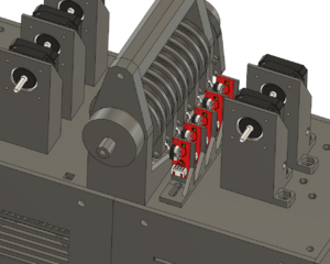
12. Connect the switches to the wires.
13. Place the switches in the switch holder. Ensure you hear a "click" to confirm they are well positioned.
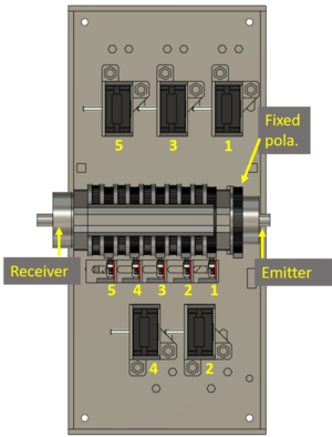
14. Connect the step-motor wires to the step-motor drivers through the RAMPS 1.4. Check the pinouts connection through its colour and according to the information provided in the subsection Step-motor drivers.
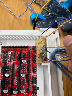
15. Assemble the detector and photodiode electric circuit.
File:Photodiode circuit.jpg Detector and photodiode electric circuit schematics. |
16. Place the electric circuit in the box corner, position it according to the holes, and bolt it.
17. Get the top part of the Arduino Mega box and bolt it to the bottom part (attention to the wires when closing the box).
18. Repeat the step 2 for the right floor.
19. Place the power supply on the right floor and secure it with bolts.
20. Get the bottom part of the Raspberry Pi box and repeat the step 4.
21. Bolt the Raspberry Pi to the box.
22. Connect the middle part of the Raspberry Pi box to the bottom part.
23. Place the cover to close the box.
Step-motor drivers
The step-motor drivers can have multiple design outputs according to the producer. The stepper pin-outs are numbered from 1-6, from left to right from the front view (shaft pointing you, connector downwards). The driver's location on the arduíno mezzanine relates to the step-motor according to the schema below:
| 5 | 3 | N/A |
| 1 | 2 | 4 |
By using a proper cable the connections should follow the table below:
| Motherboard pin-out | Cable color | Step-motor pin (A4988) | Step-motor pin (DRV8825) |
|---|---|---|---|
| 2B | Red | 6 | |
| 2A | Green | 3 | |
| 1A | Black | 1 | |
| 1B | Blue | 4 |
Light source and detection
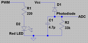
The red LED is fed by a PWM output pin (A4) from the main controller board, which allows for a variable light intensity. The default PWM from the board has a 490Hz modulation in steps of 1/256, giving a resolution of less than 0.5%.
After passing the cascade of polarizers, the signal is detected by a photodiode. This photodiode is inversely biased with a resistor to ground in order to have a zero signal when no light is present.
As the signal is modulated and its frequency has to be removed we use a low-pass first order RC-filter. As the time constant is ~1s, is necessary to delay the first acquisition for the settling of the circuit voltages. Then, as the signal varies smoothly and slowly due to the polarizer rotation, and oversampling is in place, a much lower settling time is needed.
Optical path
The optical path consists of a light source (1) (red LED) placed in the focal point of a semi-spherical lens (2) where the light rays are collimated in a parallel beam of light.
Then it is polarized by the fixed polarizer (3) before entering the cascade of variable tilt polarizers (4). This chain will dim the light according to each polarizer angle and it passes the second lens in order to focus on the detector, a photodiode (6).
Before reaching the photodiode, light may pass a red filter (5) to narrow the bandwidth and limit external noise. This filter is not damned necessary and can be replaced by red cellophane paper or even absent in case of a fully opaque plastic structure.
Optical path alignment
The main body of the device has the light propagating in parallel rays through the cascade of polarizers. Those rays are later focused on the sensor (photo-diode). It is crucial for a good signal-to-noise reading to have the system perfectly aligned. For that end, the linear position of the emitting LED and the photo-diode receiver can be adjusted according to the following procedure:
- First assemble the system lens and the light source (LED);
- Energize the LED and follow the emerging circular image from the output, eg. projecting it in a wall a couple of meters apart;
- Move the LED position in order to have an output image closer to the size of the exit circle (~30mm);
- Install the structure for the cascade of polarizers without any lens or hard film in it;
- Put in place the second collimating lens in order to focus the light in the photo-diode;
- Using a voltmeter for reading the collected light intensity to the photo-diode terminals, move back and forward the photo-diode position in order to maximize the signal;
- Firmly glue the light source and photo-diode positions in their final position.
Optical path calibration
Once the support structure is in place, is necessary to calibrate the absolute position of each polarizer; effectively all the polarizers will have a small offset giving a systematic error. It is important to note these angular value that maximizes the transmissivity.
The first polarizer is fixed and shall be positioned with a couple of degrees in order to avoid starting the experiment from a maximum, allowing for easy observation of such maxima. Consider having it around ~15º to 30º and well secured, eventually with glue. Then start the calibration procedure by inserting the second polarizer and rotating it until the maximums are detected and measured (usually two). Take note of their value and leave the second polarizer at rest in the measured position. Now insert the third polarizer and repeat the procedure for the detection of the maximums and do this for the rest of them. Every time a hard film or lens is installed it has to be firmly fixed or glued. If glue is used it must not damage the polarizer film.
You will end up with a table of maximum transmission angles, leading to the reference value of maximum intensity in the cascade of polarizers.
It is provided in the firmware a function able to rotate a set of polarizers in conjunction with each other. With this procedure local maximums can be inferred to confirm the previous determined values. In fact, if a group of the last polarizers are made to rotate in conjunction, the maximum is dictated by the first one to rotate in order to the last one fixed.
Later, when performing the experiments these values of offsets must be considered in order to eliminate the systematic error of the system.
Software
To properly use the experiment, commands and data retrieval have to be in place. This can be achieved in two ways acting through the serial connection to the Arduino Mega.
The firmware existing in the Arduido is able to (i) configure the experiment (ii) run and retrieve the generated data and (iii) execute some specialized function in order to test, calibrate and maintain the experiment. To interface with the firmware it can be used (i) a python proxy code (high-level software layer) capable of interoperating with the FREE server or (ii) a terminal emulator like Minicom available for Linux that allows you to send and receive data over the serial connection.
Raspberry FREE proxy
The Raspberry Pi is responsible for transmitting the video feed of the experiment and establishing communication with the FREE-Server by using a proxy interface. The FREE hosts the graphical user interface (GUI) to the clients. This section provides a concise overview of the procedure used to control all electronic components via the Arduino, as well as the communication protocols between the Arduino and the FREE-Server.
Communication model between the FREE-Server and the Raspberry PI
The communication between the server and the experiment follows the elab’s structured protocol that enables real-time interaction and data exchange. The central server, Exp Server, acts as an intermediary between users and the experimental apparatus (RPi Server). Users interact with Exp Server via a web interface made with Django, a high-level Python web framework, to configure and control the experiment parameters, while Exp Server directly relays these commands to the experimental setup. The communication between Exp Server and RPi Server occurs over the internet using JSON-formatted messages, ensuring flexibility across different experimental configurations. Authentication is performed at the connection stage, where the RPi Server transmits an ID and a secret key for verification. Once authenticated, the Exp Server sends an experiment-specific configuration file to the RPi Server, which then establishes communication with the local controller using the predefined protocol [7]. Throughout the experiment, the RPi Server continuously exchanges status updates, experimental results, and error messages with the XP server, ensuring synchronized operation and real-time data accessibility for users.
Communication model between the Raspberry PI and the Arduino Mega
To enable seamless communication between the Arduino and the Raspberry Pi 4, the protocol ReC Generic Drive 11 was implemented, allowing the external user to have full control over the experiment and its status through a set of commands. The ReC Generic Drive is a generic communication protocol designed for remote laboratories, facilitating interaction between a software driver and experimental hardware. It enables seamless communication over serial ports (RS232), using structured messages where driver commands are in lowercase and hardware responses in uppercase.
The protocol ensures synchronization through message handshaking and timeout handling, supporting functions like identification, configuration, data transmission, experiment configuration, and error reporting.
Fig. 11: ReC Generic Drive State-machine diagram of the driver [7]
By reading the Arduino’s serial port at a baud rate of 115200 bits per second, the user sends a bit string (ending with the character ’\r’). The configuration message is defined as:
cfg p0 p1 p2 p3 p4 p5 p6 p7\r
Where p0 defines the state of the LED (on or off), p1 p2 p3 p4 and p5 define the angle (in steps of 0.36◦) at which the experiment will start the sweep, p6 defines what polarizer will be sweeping (if does not pretend to sweep then p6 is 0) and p7 defines the limit angle of the polarizer being swept (also in steps of 0.36◦) at which the experiment will stop.
Firmware
The programming was done using the C++ language without any external libraries. To declare a component in the code, one simply provides the corresponding input pin and accesses the enable function to initialize it, as well as the isTrigger function to check whether the logical value read corresponds to the component’s trigger state. In this particular case, the switch is active on a LOW signal. Since all objects and respective components need to be initialized and turned off, each has corresponding enable/disable functions. Components connected to single read pins, declared as pinMode (such as switches and photodiodes), do not require a disable function since pinMode does not prevent reading the pins but rather helps define the type of input being processed.
In order to rotate the stepper motors, the operation consists of sending a pulse each time a rotation of 1.8◦ (0.36º effective) is desired. Since different RPM values require different pulse intervals, the frequency of sent pulses must be calculated accordingly. To execute a discrete sequence of steps based on a given angle in degrees, the rotate function was implemented. The motor rotates to the low nearest integer multiple of 1.8◦ to the provided angle.
The data acquisition interval is crucial for the final experiment since the goal is to optimize the user experience by minimizing waiting times when retrieving the intensity of light and scanning angle data. To address this, a global RPM of 600 revolutions per minute was used. With a scanning limit of 324◦ (as previously mentioned in Section III), the experimentally measured data acquisition time for scanning one or more polarizers simultaneously was approximately 40 seconds.
To further refine the voltage readings from the photodiode, an arithmetic mean of N points was implemented in the photodiode voltage reading function. By computing the arithmetic mean over 13 points of the value being measured, the standard deviation of this mean reduces the original standard deviation by ≈ 27.14%. This reduction was deemed acceptable for the experiment, as the data adjustment performed was successful, as will be observed in Section V).
